Geometrical Tolerances
Geometrical
tolerances control the geometry in drawing. Perfect geometry or close
geometrical relations improve functionality.
There
are following geometrical tolerances which are classified according to their
use in different situations.
To control the form of geometry
1-Straightness 2-Flatness 3-Cylinder
city 4-Circularity
To control orientation of
geometry
5-Parallelism 6-Perpendicularity 7-Angularity
To control the profile of
geometry
8-Profile
of a surface 9-Profile of a line
To control the run out
10-Circular
run out 11-Total Run out
To control the location of
geometry
12-Position 13-Concentricity 14-Symmetry
Let
us now see definition, where to use and how to assign each type.

Form controlling geometric
tolerances‘
These tolerances ask us to maintain the
outline of a profile. They have no
relation with any center or any datum.
They are defined by them selves only.
1-Straightness
Definition
In the image shown here the straightness
error is of 0.05 mm.

A kind of bent profile is not acceptable
if a diff. in between
two extreme bend points is 0.05 mm.

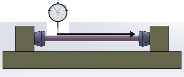
How to measure it.


How to show this in drawing
This is a mold tool ejector pin and it's
straight ness along the diameter
2.00 mm
Is needed in between 0 to 0.02. plus or minus.

1-A fixture manufactured with a very high
precision will give exact straightness value. Ensure that pin does not swivel
during testing.
2-Start the dial indicator from one side
and move it towards other end slowly.
Note the deviation of indicator.
Calculate the diff between min. and max. values.
3-A fixture will give wrong result if it
is manufactured at precision
less than 0.02 mm

2-Flatness
Definition
It defines the straightness of flat
surface.
In the first image, the surface area
covered by length and width of
rectangular top surface is having bend,
twist or irregularity of 0.05 mm.

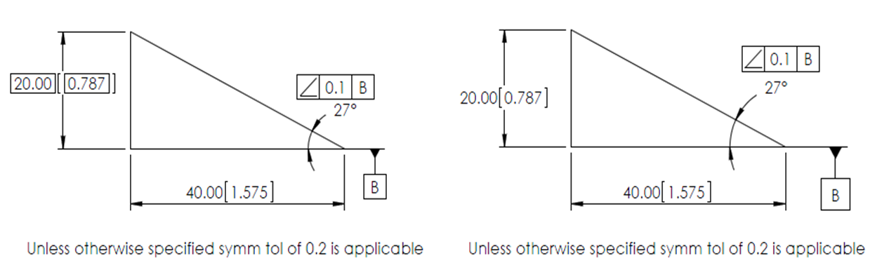
How to show this in drawing
These are shown in a box and leader
placed on the face where
flatness in critical to quality.

How to measure it
Place
the plate on surface plate. Move dial probe on whole surface area. Note the
highest and lowest reading.
Another
method is applying a blue paste on one of the plates, mate them as to be mated
in real time, if all the blue gets transferred on second plate, then plates are
flat enough. How ever this method will
give
result as “Yes” or “No” only.
Straightness
is applicable to straight profile and flatness is applicable to planar surface.
Both
the terms govern the bent or twisting occurring during normal
usage.
Is Straightness/Flatness related to s/f
finish?
No a
s/f with bad finish will have irregularity as shown in last image.
So
separate instruction shall be given to sensitise the manufacturer
about
surface finish.


